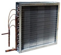
 Designed to deliver maximum heat transfer efficiency, Direct Expansion Coils are also known as “Evaporator” coils. They can be used both as an evaporator (cooling coil) and condenser (heating coil). Compared to a chilled water system, in a direct expansion coil system, a treated airstream passes through the outside of the evaporator coil, allowing it to be directly cooled by the expansion of refrigerant passing through the tubes of the coil, without using water.
Direct Expansion Coil Specifications
Round seamless copper tubes are mechanically expanded into the fin collars of the secondary surface. The mechanical expansion provides a permanent metal-to-metal bond for efficient heat transfer. Tubes are staggered in the direction of airflow and only return bends are used – NO reduced tube wall in the bend radius by using hairpin bends.
Tube Size Options
5/8″ O.D. x .020″ wall thickness standard with optional wall thickness of (.025) (.035) and (.049). Centerlines are 1.5″ in the tube face and 1.299″ between rows.
1/2″ O.D. x .017″ wall thickness standard with optional wall thickness of (.025). Centerlines are 1.25″ in the tube face and 1.083″ between rows.
3/8″ O.D. x .016″ wall thickness standard with optional wall thickness up to (.035). Centerlines are 1″ in the tube face and .866″ between rows.
Rows available are 2, 3, 4, 5, 6, 8, 10 and 12.
We have over 20 different surfaces available. Please contact us if construction other than what is above is needed.
Corrugated plate type fin that is die-formed. Fin collars are full-drawn to provide accurate control of fin spacing and maximum contact with tubes.
Fin Material Options
5/8″ tubes comes standard with aluminum fin .008″ thick with optional (.010). Optional copper fin thicknesses available are (.006) (.008) and (.010). Fins per inch available 8 through 14.
1/2″ tubes come standard with aluminum fin .006″ thick with optional copper fin (.006). fins per inch available 8 through 14.
3/8″ tubes comes standard with aluminum fin .0055″ thick with optional thicknesses available. Copper fin thicknesses available start at .0055″.
Fins per inch available 6 through 16.
Contact us for availability of other patterns, fin materials, and/or thicknesses.
Seamless copper with die-formed holes that provide a parallel surface to the coil tube for strong brazing joints.
All coil assemblies are leak tested under water at 315 PSIG air. Standard construction is suitable for 250 PSIG and up to 300 degrees F.
PERFORMANCE IS CERTIFIED under ARI Standard 410. All coil performance ratings are according to Commercial Coils, Inc.’s ARI certified selection software.